
Introduction
Getting ESD bench grounding wrong doesn't announce itself. Component failures, failed audits, and latent damage that surfaces weeks later in the field — these are the real costs of a setup that looks correct but isn't.
Most setups are handled by trained in-house technicians or facilities engineers, and the common mistakes rarely involve missing equipment. They involve incorrect connection sequences, shared grounds that create safety risks, or incomplete coverage that leaves the operator ungrounded while the bench surface is fine.
According to the EOS/ESD Association, ESD costs the average electronics manufacturer 4% to 8% of annual corporate revenue — a figure that includes both immediate failures and the harder-to-trace latent defects that show up weeks later in the field.
This guide covers:
- Pre-setup requirements before you connect anything
- The correct grounding sequence per ANSI/ESD S6.1
- Post-setup validation and testing
- The most common grounding mistakes
- Long-term maintenance practices
TL;DR
- ESD bench grounding creates a controlled, low-impedance path for static electricity to safely dissipate — preventing component damage and reducing operator shock risk.
- Per ANSI/ESD S6.1, all bench elements connect to a common point ground (CPG) first — the CPG then ties to the equipment grounding conductor.
- Wrist strap cords must include a 1 megohm resistor for current limiting — floor mat and worksurface cords generally do not.
- Ground every element: bench surface, operator, floor mat, and conductive accessories.
- Test all connections before first use and verify wrist straps at the start of every shift.
Before You Begin: Standards, Prerequisites, and Materials
The Two Governing Standards
Two standards define the framework for ESD bench grounding:
- ANSI/ESD S6.1-2019 — Specifies parameters, materials, equipment, and test procedures to choose, establish, verify, and maintain an ESD grounding system within an ESD Protected Area (EPA).
- ANSI/ESD S20.20-2021 — The program-level framework covering training, product qualification, compliance verification, and auditable records. S6.1 handles the mechanics; S20.20 governs the program.
Before setup, identify the HBM and CDM withstand voltage ratings for the devices handled at the bench. CDM classes begin at 125V (Class C1), and charged-device events are the leading cause of ESD damage in modern electronics manufacturing — a CDM discharge can complete in under 1 nanosecond and reach several amps.
Site Readiness Checklist
Confirm the following before ordering materials or beginning installation:
- Designated EPA with boundary markings in place
- Verified equipment grounding conductor (third-prong AC ground) at the workstation — test with a socket tester
- Dedicated ESD earth ground point, separate from the AC safety ground
- ESD-rated flooring or floor mat coverage at the operator position
Required Materials
| Item | Specification |
|---|---|
| ESD worksurface | Static-dissipative, 1×10⁶ to 1×10⁹ ohms per ANSI/ESD STM4.1 |
| Worksurface grounding cord | Route to CPG; check manufacturer spec on resistor requirement |
| Wrist strap with resistor cord | 1 megohm, min. 1/4 watt, 250V working voltage per ANSI/ESD S1.1 |
| Common point ground (CPG) block | Single hub for all ESD ground connections at the bench |
| Floor mat with ground snap | Connected to CPG or earth ground |
| Socket tester | Verify AC outlet ground before proceeding |
Bench selection affects how much of the above you'll need to source and install yourself. Workplace Modular Systems' Custom ESD Workstation Systems come with factory-installed grounding hardware — a flush-mounted ground bolt with a 6-foot ground wire and a bench mount for two wrist straps — which removes the field installation steps that most commonly introduce errors.
How to Ground an ESD Workbench: Step-by-Step
ANSI/ESD S6.1 defines a specific two-step sequence: first, connect all bench elements to the common point ground; then, connect the CPG to the equipment grounding conductor. Reversing or skipping this sequence creates potential differences between elements — exactly the condition that triggers CDM-type damage.
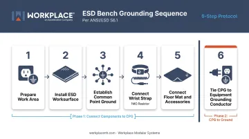
Step 1: Prepare the Work Area
- Confirm the bench is positioned within the designated EPA
- Test the AC outlet with a socket tester — the ground pin must be functional
- Identify or install the dedicated ESD earth ground point (separate from the power ground)
Step 2: Install and Connect the ESD Worksurface
Place the ESD mat or confirm the laminate worksurface is ESD-rated. Then:
- Connect the worksurface grounding snap or lug to a grounding cord
- Route this cord to the CPG block
Note: ANSI/ESD S6.1 recommends non-resistor grounding cords for worksurfaces and floor mats. Resistors in these paths are not required the way they are for wrist straps.
Step 3: Establish the Common Point Ground
Install the CPG block at the bench: this is the single connection hub for all ground cords. Label it with the ANSI/ESD S8.1-2021 ESD common point ground symbol. Every grounding cord at the bench — worksurface, wrist strap, floor mat, accessories — terminates here.
Step 4: Connect the Wrist Strap
Connect the wrist strap cord from the operator's wrist band through its 1 megohm resistor to the CPG. Without this connection, charge builds on the operator's body and discharges into components on contact. The shared ground path keeps operator and bench surface at the same electrical potential.
The 1 megohm resistor in this path is for current limiting and operator safety: it limits current to less than 0.5 mA at the highest voltage encountered.
Step 5: Connect the Floor Mat and Accessories
- Run a grounding cord from the floor mat's ground snap to the CPG or directly to the earth ground
- Ground conductive accessories — shelving, bin rails, tool holders — individually if they are not already bonded through a verified conductive bench frame
- If the bench frame is confirmed conductive and grounded, accessories in solid mechanical contact with it may be bonded through the frame; otherwise, run a separate ground wire
Step 6: Tie the CPG to the Equipment Grounding Conductor
Connect the CPG to the AC equipment ground (green wire / third prong) at the workstation outlet. This brings all ESD elements to the same reference potential as the electrical equipment at the bench.
One additional requirement: any auxiliary ground present (water pipe, building frame) must be bonded to the equipment grounding conductor. Unbonded parallel ground paths create the potential differences that ESD controls are designed to eliminate.
Post-Setup Validation and Testing
A bench that looks grounded can still harbor potential differences between elements. Those differences won't show up until a component is placed across them, often resulting in latent failures that surface weeks later as field returns.
Structured validation catches those gaps before they reach production. Work through visual checks first, then move to functional testing.
Visual and Continuity Checks
Before any functional testing:
- Inspect all cord connections for secure fit
- Verify the CPG label is in place (ANSI/ESD S8.1 symbol)
- Confirm no conductive elements are floating — unconnected metal parts, non-grounded shelving, or disconnected accessories
Functional Testing
ESD TR53-01-18 is the compliance verification reference for this testing:
| Test | Method | Acceptance |
|---|---|---|
| Worksurface resistance | Point-to-point and resistance-to-ground per STM4.1 | 1×10⁶ to 1×10⁹ ohms |
| Wrist strap system | Wrist strap tester, worn by operator | 0.8 to 1.2 × 10⁶ ohms per ANSI/ESD S20.20 Table 3 |
| Floor mat / flooring-footwear system | Resistance to ground | Less than 1.0 × 10⁹ ohms; walking voltage less than 100V |
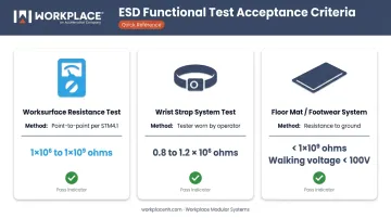
Always test the wrist strap while the operator is wearing it. The tester evaluates the band, ground cord (including the resistor), and skin contact as a complete system.
Ongoing Testing Requirements
- Wrist straps: Test at the start of each shift, or install a continuous wrist strap monitor if device sensitivity requires real-time fault detection
- Ground paths and worksurface: Verify at defined intervals as part of a written ESD control program
- Verification records: All compliance verification results must be documented and maintained as evidence per ANSI/ESD S20.20 — daily wrist strap logs are a standard audit item
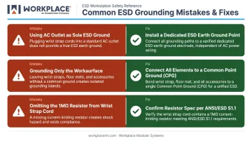
Common ESD Grounding Mistakes and How to Fix Them
Most grounding failures aren't caused by missing equipment. They come from incorrect connections, shared grounds, or incomplete system coverage.
Mistake 1: Using the AC Electrical Ground as the Sole ESD Ground
Problem: Grounding ESD equipment directly into the wall outlet's ground pin creates the risk of high-voltage backflow during an electrical fault — and it confuses two systems that serve different purposes.
Fix:
- Install a dedicated ESD earth ground point separate from the power circuit
- Bond it to the equipment grounding conductor to equalize potential
- Route all ESD control cords to that dedicated point — not into the power socket
Mistake 2: Grounding Only the Worksurface
Problem: Even with a perfectly grounded bench surface, an operator who hasn't connected their wrist strap is accumulating charge through normal movement. That charge discharges directly into components on contact.
Fix:
- Connect every element — wrist strap, floor mat, conductive shelving, and tools — to the common point ground (CPG)
- Conduct a full-system resistance check at commissioning
- Re-verify after any changes to the workstation layout
Mistake 3: Omitting the 1 Megohm Resistor from the Wrist Strap Path
Problem: A direct wire connection from wrist strap to ground with no resistor removes the current-limiting protection — and eliminates the safety margin that prevents dangerous current from passing through the operator.
Fix:
- Confirm all wrist strap cords include a 1 MΩ, minimum ¼W, 250V resistor per ANSI/ESD S1.1
- Check for built-in resistors before purchase
- Verify compliance before installation — not after
Best Practices for Long-Term ESD Grounding Performance
Control the Environment
Humidity has a direct impact on static charge buildup. ANSI/ESD S20.20 and IEC 61340-5-1 require qualification of ESD control items at 12% ±3% RH at 23°C ±3°C — the lowest-humidity threshold at which products must still meet their specifications. In practice, very low humidity dramatically increases static charge generation.
When environmental control is limited, ionizers can neutralize charge on insulators and isolated conductors that cannot be grounded. Humidification supplements grounding but cannot replace it.
Establish a Documented Inspection Schedule
A compliant ESD control program under ANSI/ESD S20.20 requires auditable records. Build a testing and inspection log that includes:
- Daily: Wrist strap testing (or continuous monitor logs)
- Weekly/Monthly: Ground cord integrity checks, worksurface resistance verification
- After changes: Full-system resistance check whenever the workstation layout is modified
Facilities pursuing ANSI/ESD S20.20 certification need this documentation audit-ready at all times. Purpose-built ESD workbenches with factory-installed grounding systems (such as those from Workplace Modular Systems) reduce the number of field-installed connections that need tracking, which simplifies long-term compliance verification.
Train Operators, Not Just Technicians
A correctly grounded bench fails the moment an operator skips the wrist strap, reaches for a non-ESD tool, or disconnects a ground cord to reroute a cable. Build ESD grounding awareness into initial onboarding and schedule refresher training after any significant changes to workstation configuration, personnel, or processes. ESD compliance is a system behavior — it depends on every person who touches the bench.
Frequently Asked Questions
How do you properly ground an ESD workbench?
Follow the two-step ANSI/ESD S6.1 sequence: connect all bench elements — worksurface, wrist strap, floor mat, and conductive accessories — to a common point ground block, then connect the CPG to the equipment grounding conductor at the workstation. Always include a 1 megohm resistor in the wrist strap cord.
Which ESD items should be grounded?
Every conductive element in the EPA: the ESD worksurface, the operator (via wrist strap or footwear/floor system), the floor mat, and any conductive accessories such as shelving, bin rails, and tool holders. If conductivity through the bench frame is unverified, run individual ground wires.
What are common grounding mistakes on ESD benches?
The three most frequent errors are:
- Using the AC power outlet as the only ESD ground
- Grounding only the bench surface while leaving the operator ungrounded
- Omitting the 1 megohm resistor from the wrist strap grounding cord
What is an ESD control system?
An ESD control system coordinates grounded surfaces, operator grounding, ESD-rated materials, and documented procedures to bring all elements to the same electrical potential, eliminating the charge difference that triggers damaging discharges. Grounding alone isn't sufficient without supporting program documentation.
What is the role of an ESD work surface mat, and are there alternatives?
ESD mats provide a dissipative, grounded work surface to safely channel static charges from components and tools to ground. Alternatives include ESD laminate worksurfaces and ESD-rated bench surfaces, each with different resistance properties and grounding implications. Verify each option against ANSI/ESD STM4.1 before use.
Which materials are ideal for ESD-protected areas?
Use static-dissipative worksurfaces and mats, conductive or dissipative packaging, ESD footwear, grounded wrist straps, and dissipative storage containers. Avoid purely insulative materials (cannot be grounded) and purely conductive materials without proper resistor protection. Conductive bench frames are acceptable when bonded to the CPG with verified continuity.